Form Editor
Objectives
- Graphical editing of data fields and headings within a form
- Changing the layout via the context menu or menu items
Open the Form Editor
Procedure
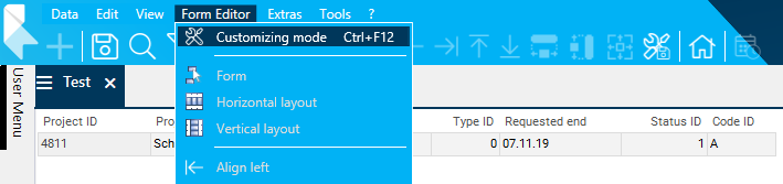
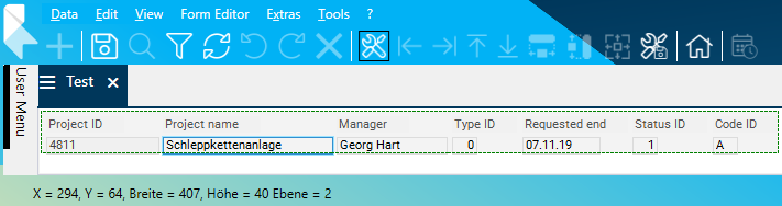
- Activate the customizing mode via Form Editor Customizing mode.
- Alternatively, the Customizing mode button in the toolbar can be used.
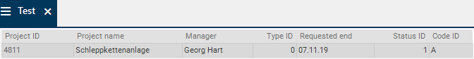
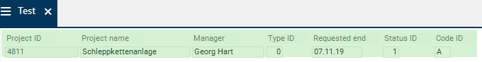
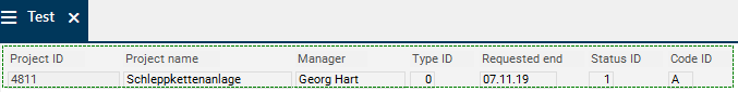
- As a result, the data areas with Layout = 0 (horizontal layout) or Layout = 1 (vertical layout) gray, that are marked green with Layout = 2 (form).
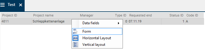
- If the data area to be edited has a horizontal or vertical layout, change the layout to form by selecting the Form command from the context menu or via the Form Editor Form menu item.
- If the data area to be edited is already a form, activate the area by clicking on the data area.
- As a result, the green mark disappears and the form area is surrounded by a dashed line and can be edited.
Graphical Editing
General Information on Graphical Editing
From C 39.5.19
Information
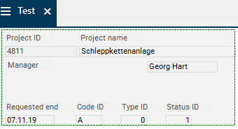
- By positioning the cursor over an element, it is framed with a thin, light-blue line.
- An element is marked by left-clicking on it.
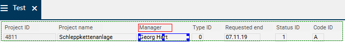
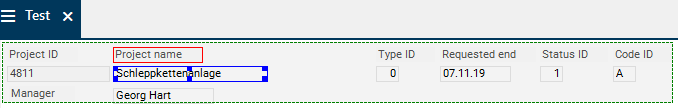
- Data fields (heading fields) are framed with a dark-blue (light-blue) line on which, depending on the size of the element, four to eight squares (edge markings) are located.
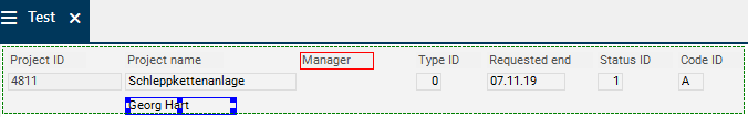
- If a data field (heading field) is marked, the corresponding heading field (data field) is framed in red.
- There are two ways to mark several elements:
- Click on the required elements separately and successively by left-clicking and holding CTRL.
- Mark several elements in an area.
- By pressing and holding the SHIFT button and the left mouse button and moving the mouse, a frame is drawn around the corresponding area.
- When releasing the left mouse button, all elements that lie within the frame, are marked.
- In order to add other elements to the already marked elements in the same way, press and hold CTRL additionally.
- If several elements are marked, the last marked
- data field is framed in blue, the other marked fields are framed in black.
- heading field is framed in light blue, the other marked heading fields are framed in gray.
- If the data field and the corresponding heading field are marked, the heading field is framed in light-blue and the data field is framed in dark-blue, regardless of what was marked last.
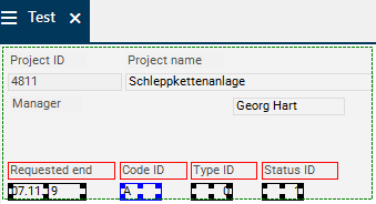
- By pressing the TAB button, all elements, i.e. all data fields and heading fields in the activated area are displayed with a red frame. As a result, you can see, e.g., the actual size of elements that have no frame or elements that are in the background.
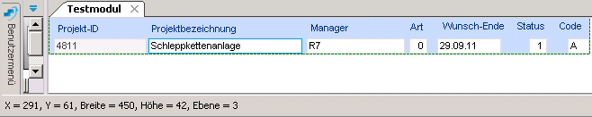
- By positioning the cursor over an element or by marking an element, its coordinates, size, and level are displayed in the status line. NEW When changing the size and position of an element with the mouse, these specifications are additionally displayed in a tooltip on the element. This information helps e.g. to recognize the smallest deviations on positioning or size of the elements in order to correct them if necessary.
- For cascading elements, the element in the foreground has a higher level. With the In the foreground or In the background menu items, the level of the marked elements is changed, whereas the elements that are displayed in the foreground receive the higher level.
Up to C 39.5.19
Information
- By positioning the cursor over an element, it is framed with a thin, light-blue line.
- An element is marked by left-clicking on it.
- Data fields (heading fields) are framed with a dark-blue (light-blue) line on which, depending on the size of the element, four to eight squares (edge markings) are located.
- If a data field (heading field) is marked, the corresponding heading field (data field) is framed in red.
- There are two options for marking several elements:
- Click on the required elements separately and successively by left-clicking and holding CTRL.
- Mark several elements in an area.
- By pressing and holding the SHIFT button and the left mouse button and moving the mouse, a frame is drawn around the corresponding area.
- When releasing the left mouse button, all elements that lie within the frame, are marked.
- In order to add other elements to the already marked elements in the same way, press and hold CTRL additionally.
- If several elements are marked, the last marked
- data field is framed in blue, the other marked fields are framed in black.
- heading field is framed in light blue, the other marked heading fields are framed in gray.
- If the data field and the corresponding heading field are marked, the heading field is framed in light-blue and the data field is framed in dark-blue, regardless of what was marked last.
- By pressing the TAB button, all elements, i.e. all data fields and heading fields in the activated area are displayed with a red frame. As a result, you can see, e.g., the actual size of elements that have no frame or elements that are in the background.
- By positioning the cursor over an element or by marking an element, its coordinates, size, and level are displayed in the status line. This information helps e.g. to recognize the smallest deviations on positioning or size of the elements in order to correct them if necessary.
- For cascading elements, the element in the foreground has a higher level. With the In the foreground or In the background menu items, the level of the marked elements is changed, whereas the elements that are displayed in the foreground receive the higher level.
Save changes
- The user
- A customizer
- Unsaved changes will be reset if the module is closed.
Edit Element
Move Element
Information
- There are two ways to change the position of an element:
- Drag the element to the required position by holding the left mouse button.
- or via the following key combinations:
| Key combination |
Explanation |
1) Left arrow
2. A |
The element is moved to the left in small steps |
1) Right arrow
2. D |
The element is moved to the right in small steps |
1) Arrow upwards
2. W |
The element is moved upwards in small steps |
1) Arrow downwards
2. S |
The element is moved downwards in small steps |
1) CTRL + left arrow
2. CTRL + A |
The element is moved to the left in large steps |
1) CTRL + right arrow
2. CTRL + D |
The element is moved to the right in large steps |
1) CTRL + arrow upwards
2. CTRL + W |
The element is moved upwards in big steps |
1) CTRL + arrow down
2. CTRL + S |
The element is moved downwards in large steps |
Procedure
- Activate the Customizer via Form Editor Customizing mode.
- Right-click on the element (in this case a data field) in order to mark it.
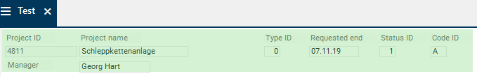
- Move the marked data field to the required position by holding the left mouse button.
- When dragging with the mouse, the current position of the data field is displayed as a gray shadow.
Details
- If an element is dragged outside the dashed form area, the form area is extended accordingly.
- Within a module, elements can be moved between the windows. E.g. from window 1 to window 2. Here, the corresponding heading fields/data fields are automatically moved as well.
- IronPython objects (e.g. battery symbols) must be marked with the frame function (SHIFT + mouse) and be moved with the keyboard.
Change Size
Information
- There are two ways to change the size of an object:
- Draw the element with the mouse:
- Left-click on an edge mark and move the mouse into the required direction holding down the left mouse button.
- Or use the following key combination:
| Shortcut |
Description |
| ALT + arrow keys (or W-S-A-D) |
Enlarges the element in arrow direction in small steps |
| SHIFT + ALT + arrow keys (or W-S-A-D) |
Downsizes the element in arrow direction in small steps |
| CTRL + ALT + arrow keys (or W-S-A-D) |
Enlarges the element in arrow direction in large steps |
| CTRL + SHIFT + ALT + arrow keys (or W-S-A-D) |
Downsizes the element in arrow direction in large steps |
Procedure
- Activate the customizing mode via Form Editor Customizing mode.
- Left-click on the element in order to mark it.
Edit Several Elements Simultaneously
Information
- The procedure for marking several elements can be found here.
- Several elements can be moved via the key combinations or using the mouse.
- The size of several elements can only be changed via the key combination (and not with the mouse, as it is possible for single elements).
Move Elements
Procedure
- Activate the customizing mode via Form Editor Customizing mode.
- Mark the elements to be moved.
Change Size
Procedure
- Activate the customizing mode via Form Editor Customizing mode.
- Mark the elements that are to be edited.
Menu Item of the Form Editor
Information
- The individual menu items can be found in the menu bar in the Form Editor menu or as buttons in the toolbar.
Align Left/Right/Top/Bottom
Information
- Via these menu items, all marked elements are aligned at the left/right/top/bottom margin of the last marked element.
Procedure
- Activate the customizing mode via Form Editor Customizing mode.
- Mark the elements that are to be aligned. Here, the element by which you want to align must be the last element to be marked.
Note
- These menu items are only available if
- more than one element is marked.
- an alignment of the elements is possible at all.
Center Horizontally/Vertically
Information
- Via these menu items, all marked elements next to the one that was marked at last, are centered horizontally/vertically.
Procedure
- Activate the customizing mode via Form Editor Customizing mode.
- Mark the elements to be centered. Here, the element by which you want to center must be the last element to be marked.
Note
- These menu items are only available if
- more than one element is marked.
- an alignment of the elements is possible at all.
Adjust Horizontal/Vertical Intervals
Information
- Via these menu items, horizontal/vertical gaps of the marked elements are adjusted in such a way that all elements have the same horizontal/vertical interval between them.
Procedure
- Activate the customizing mode via Form Editor Customizing mode.
- Mark the elements the intervals of which you want to adjust.
Note
- These menu items are only available if
- more than one element is marked.
- an alignment of the elements is possible at all.
Same Width/Height/Size
Information
- Via these menu items, all marked elements receive the width/height/size of the element marked at last.
Procedure
- Activate the customizing mode via Form Editor Customizing mode.
- Mark the elements that are to receive the same width. For this purpose, mark the element the width of which you want the marked elements to receive.
- Here, the width of the elements is to be adjusted to the width of the Status field.

Note
- These menu items are only available if
- more than one element is marked.
- an alignment of the elements is possible at all.
Horizontal/Vertical Automatic Layout
Information
- Via these menu items, all marked elements are aligned horizontally/vertically.
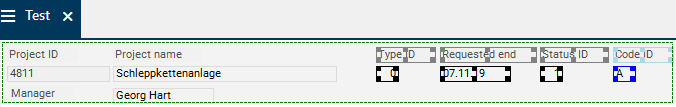
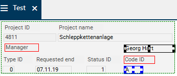
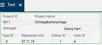
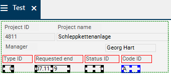
Align elements horizontally
- Activate the customizing mode via Form Editor Customizing mode.
- Mark the elements that are to be aligned horizontally. Here, the element next to which the marked elements are to be aligned, must be the last element to be marked.
- Here, the elements are to be aligned horizontally next to the Req. end field.
- Select the Form Editor Horizontal layout menu item.
- All previously marked elements are now aligned horizontally next to the last marked Req. end field.
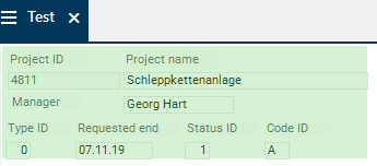
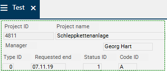
- Save the changes made in the form editor.
- Result:
- In the horizontal layout, the heading fields are aligned next to each other from left to right and the corresponding data fields below from left to right.
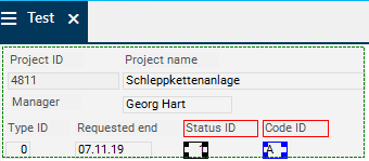
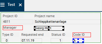
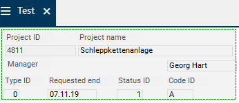
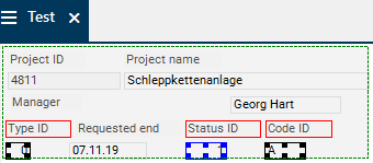
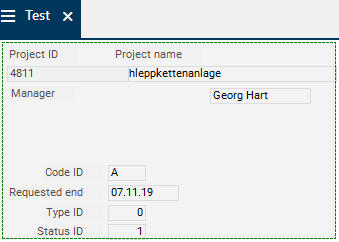
Align elements vertically
- Activate the customizing mode.
- Mark the elements that are to be aligned vertically. Here, the element below which the marked elements are to be aligned, must be the last element to be marked.
- Here, the elements are to be aligned vertically below the Code field.
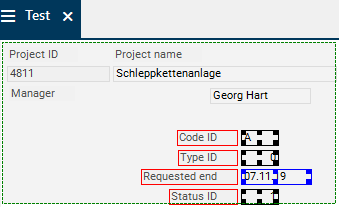
- Select the Form Editor Vertical automatic layout menu item.
- All previously marked elements are now aligned vertically below the last marked Code field.
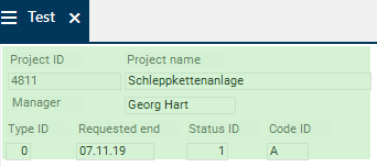
- Save the changes made in the form editor.
- Result:
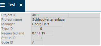
- In the vertical layout, the heading fields are aligned from top to bottom and next to them, the corresponding data fields are aligned from top to bottom.

Note
- These menu items are only available if more than one element is marked.
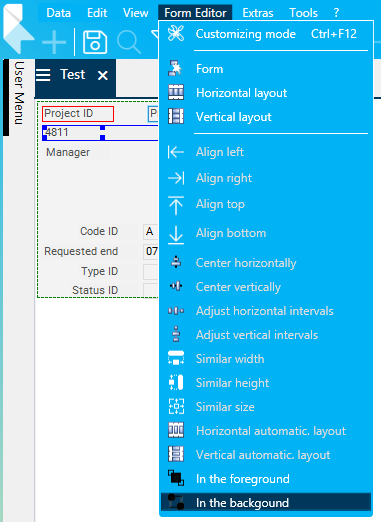
In the Foreground/Background
Information
- Via these menu items, all marked elements are moved to the foreground/background.
- For cascading fields or headings, this defines what is displayed in the foreground/background.
Procedure
- In this example, the Project ID and Project name fields cascade.
- Activate the customizing mode via Form Editor Customizing mode.
- For cascading elements, mark the element to be moved to the background (here, the Project ID field).
- Select the Form Editor In the background menu item.

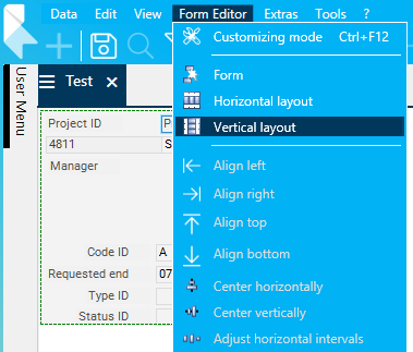
Form/Horizontal Layout/Vertical Layout
Information
- Via these menu items, the layout of the data areas can be changed.
Procedure
- Activate the customizing mode via Form Editor Customizing mode.
- Select the Form Editor Vertical layout menu item.
Details
- By selecting the appropriate entry, the layout of the data area is changed.
- If you switch from form (Layout = 2) to horizontal (Layout = 0) or vertical layout (Layout = 1), the data fields are displayed in the same order as in the data area.
- If you switch to form (Layout = 2) for the first time, the form positions of all visible data fields are automatically set according to the horizontal auto layout.
Example:
Design Data Area as a Form in Module Workflow Level 1
Context Menu Functions in the Form Editor
Display and Hide Data Fields
Procedure
- Activate the customizing mode via Form Editor Customizing mode.
- Activate the area in which data fields are to be displayed/hidden.
- Right-click into the required data area.
- The context menu is opened, in which all visible fields of the corresponding window (marked by a checkbox) and invisible fields of a module are listed.
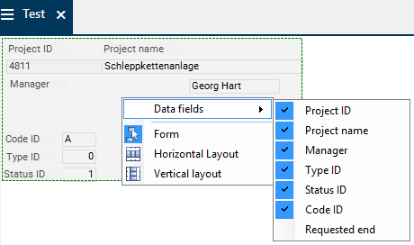
- In order to hide a field:
- Deactivate the checkbox for the field you want to hide (here, the Manager field).
- Alternatively, the data field can also be deleted with the DEL button. To do so, mark the corresponding data field and hide it via DEL.
- If a heading is hidden by clicking on DEL, the corresponding field remains visible.
- Save the changes made in the form editor.
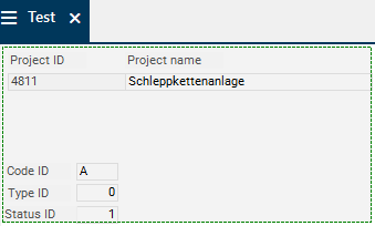
- Result:
- In order to display an invisible field:
- Activate the checkbox for the field to be displayed.

Notes
- By holding down the CTRL key, several columns can be displayed or hidden at once.
- If several elements are displayed, the heading fields and the corresponding data fields are positioned next to one another and the separate data fields are positioned one below the other.
- If a data field is hidden, the corresponding heading field is hidden automatically as well.
Details
Add New Data Fields in Form Areas
Objective
- Insert a new data field in a data area with form
Procedure
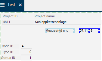
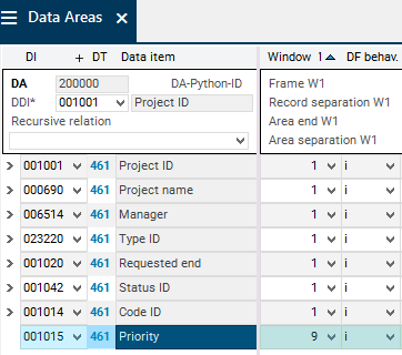
- Insert the new data field (here data field 001015 Priority) in the Data Areas module.
- Set the Window = 9.
- Activate the DF options checkbox.
- Save.
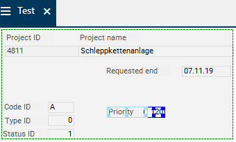
- Open the module.
- Activate the customizing mode via Form Editor Customizing mode.
- Activate the area in which the data field is to be displayed.
- Open the context menu and activate the checkbox for the new data field at the position at which the data field is to be displayed.
Note
- If the new data field is inserted in the Data Area module and the Window parameter is not set to 9 but directly to the required window (1-3), the field is displayed in the top left corner of the respective window without the corresponding heading.
Form/Horizontal Layout/Vertical Layout
Information
- Via these context menu commands, the layout of the data areas can be changed.
Procedure and details are the same as that of the menu items of the same name.
 .
. 
